Task 8
Computer controlled machining
In this week, I was given a task to have a group assignment and an Individual assignment. The group assignment was to test runout, alignment, speeds, feeds, and toolpaths for your machine, and the Individual assignment was to make (design+mill+assemble) something big
Group Task
For this week, we started with ou group work. Our Local Instructor Eino Antikainen guided us with the simulation of the design using Fusion 360 and how to get the tool paths in CAM workspace. The example for this purpose was a simple one which had some rounded and square 2D pockets and the outerline was cutting. He also gave us the instructions of prepare the machine and to cut the designed model.
The thickness of the Material OSB that we will be using is about 11mm approximately. The model was designed using fusion 360, the toolpaths were created. For CAM processing two files were being downloaded from the OULU wiki page. One file is for tool path containing tools and values and the other file is for Post Process which is used by the NC Routing Machine. The Individual assignment will discuss in detail.
Getting started with the Machine
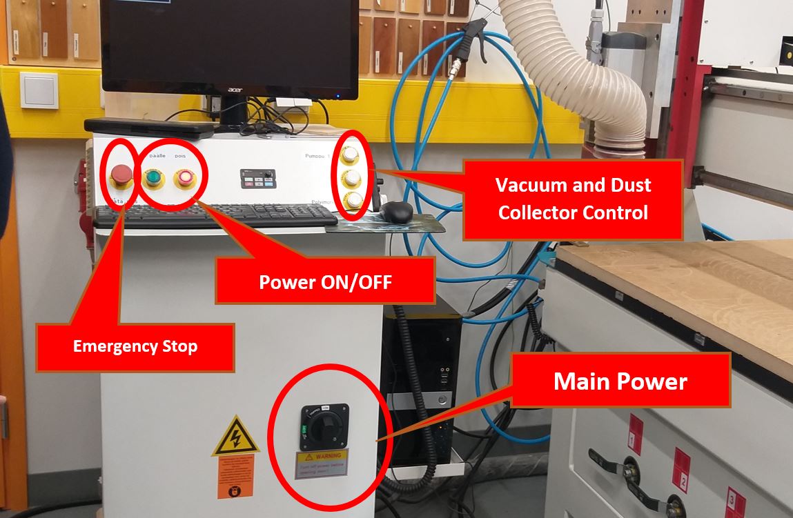
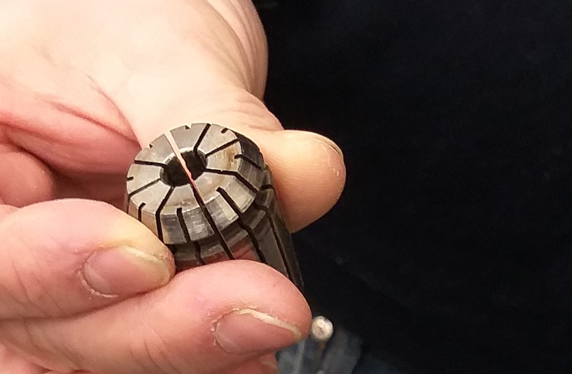
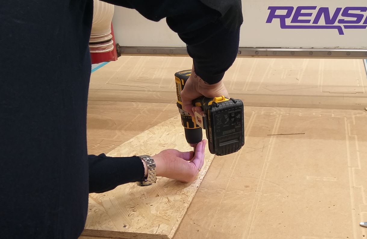
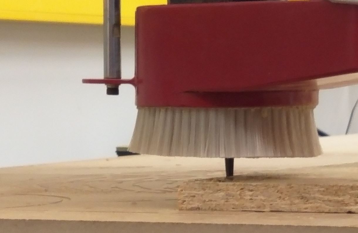
We used Rensi E2-1325 CNC router, First we turned on the main switch and power on. Then we set up the table. We attached the material, OSB, on the table with screws. Make sure the screw doesn’t go down deeper than the wooded table. We used an 8mm flat milling bit. First, we needed to attach the mill bit to the clamp before cutting. Setting the Origin is very essential before starting the milling.
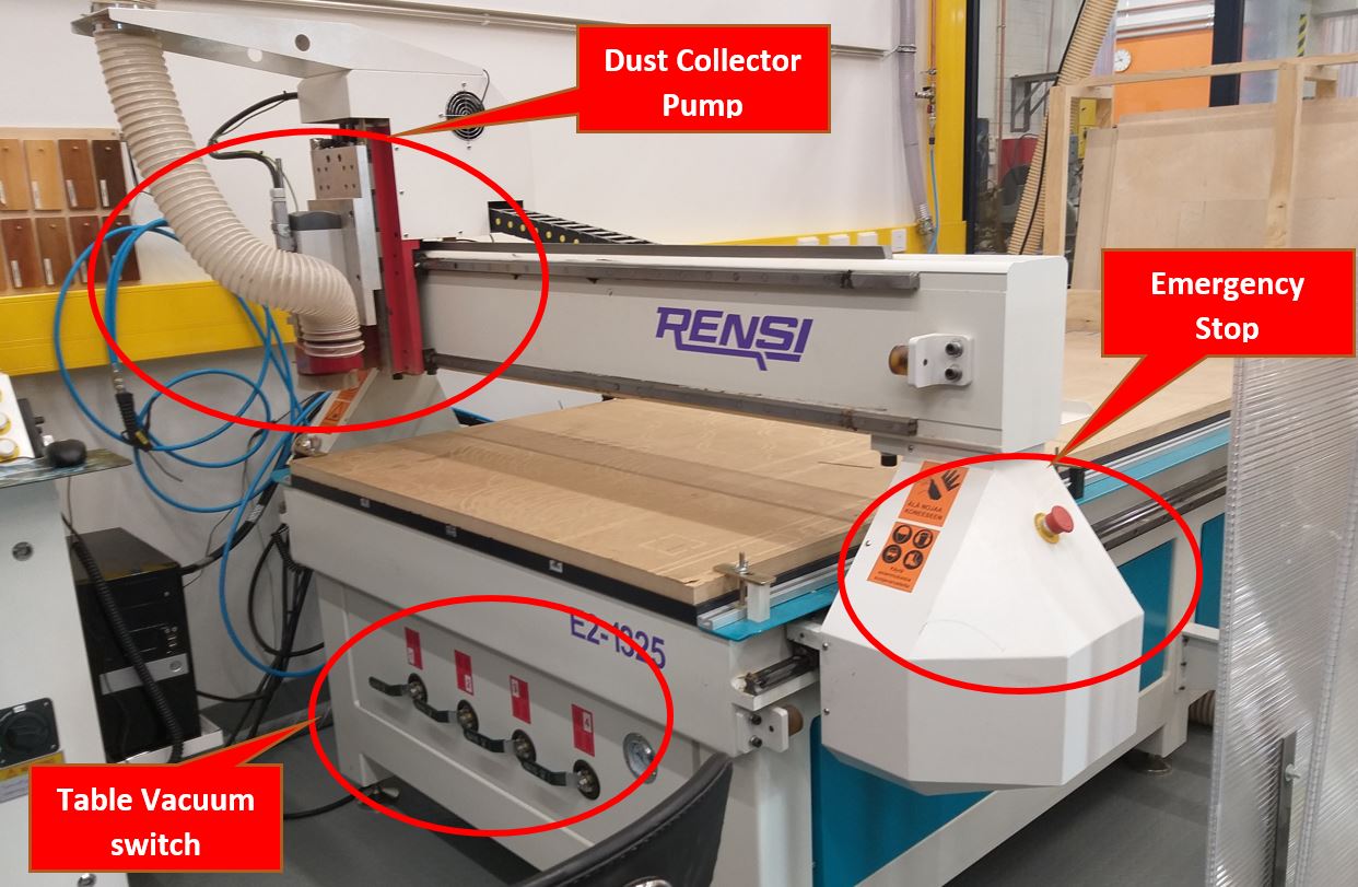
- Safety Precautions to be taken
- Go with someone, use protective googles and earmuffs.
- Do not start it until you know how to stop it
- Do not leave the machine working without supervision
- If anything goes wrong, use the Emergency stop button.
Milling Process
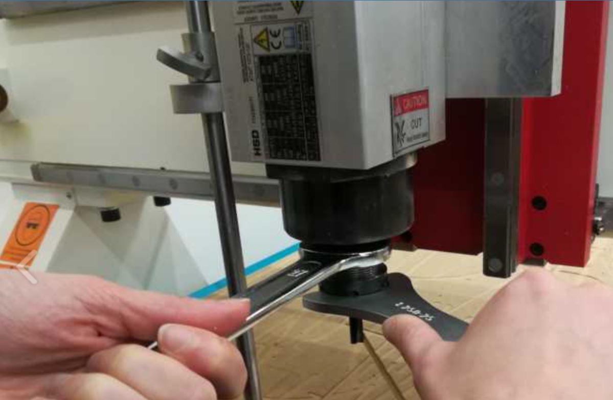
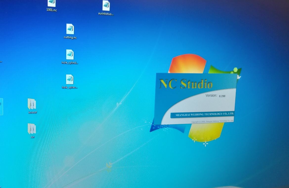
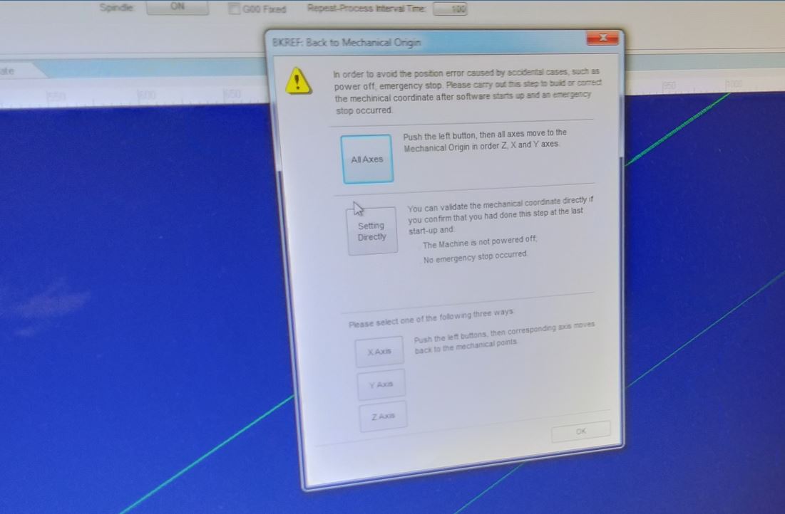
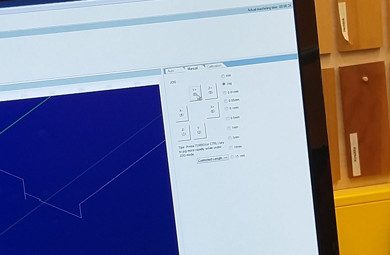
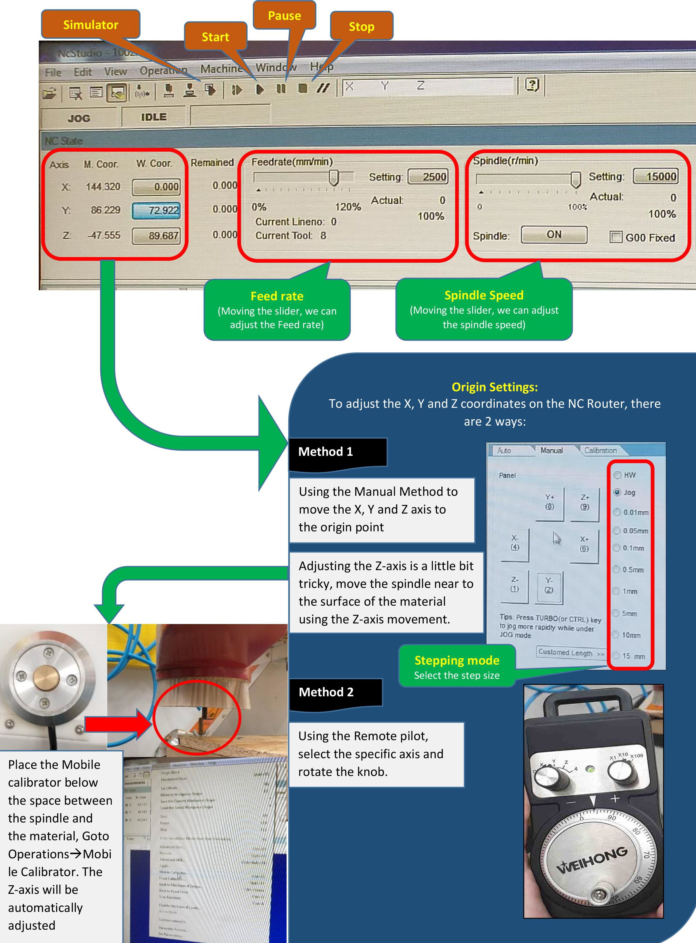
First open the CNC Studio Software. If the machine has been turned off, there is a need to build the mechanical coordinates when the software is started. In this case a pop-up window will appear during startup. Select "all axes", and the program will automatically move all axes to the correct mechanixal origin spot for the X, Y and Z axis. After it is finished, you can just press OK.When this was done, I moved the milling bit to the point in the board where I wanted to set my origin point. To set the Z origin we can use the auto calibrator. Put the calibrator below the milling bit and from the CNC studio select Operation > Mobile calibrator. Then the z-axis will be calibrated automatically.
To perform the required settings, simple and easy steps to follow:
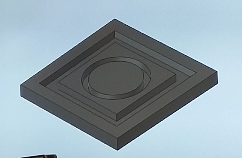
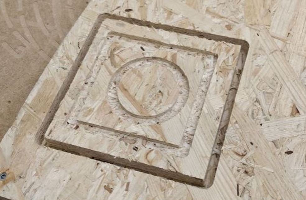
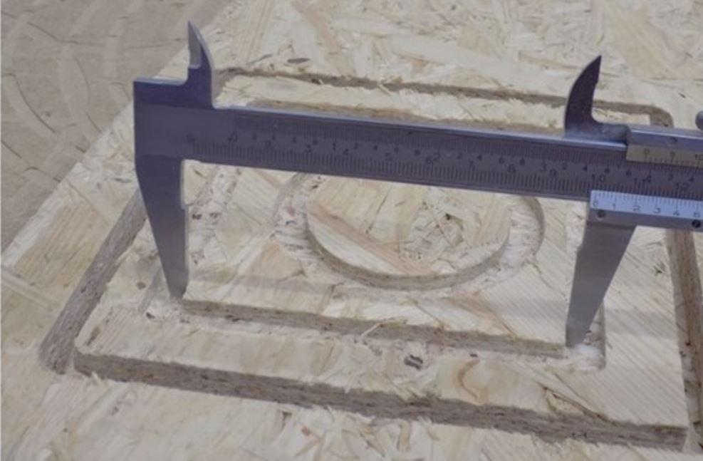
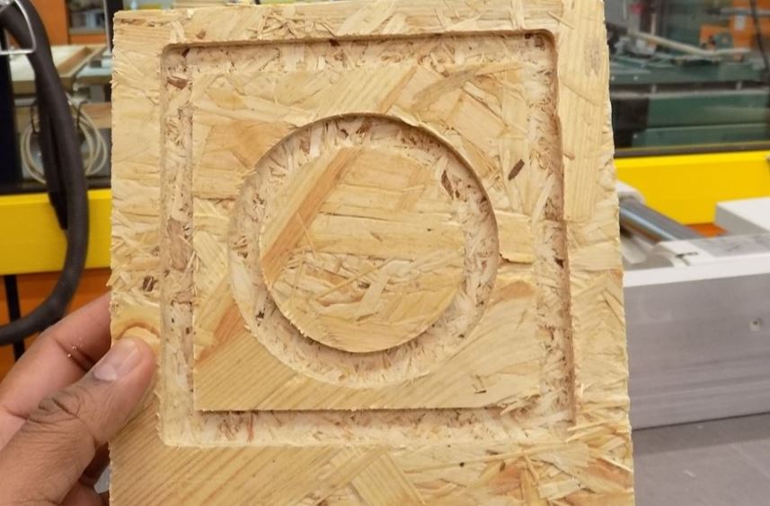
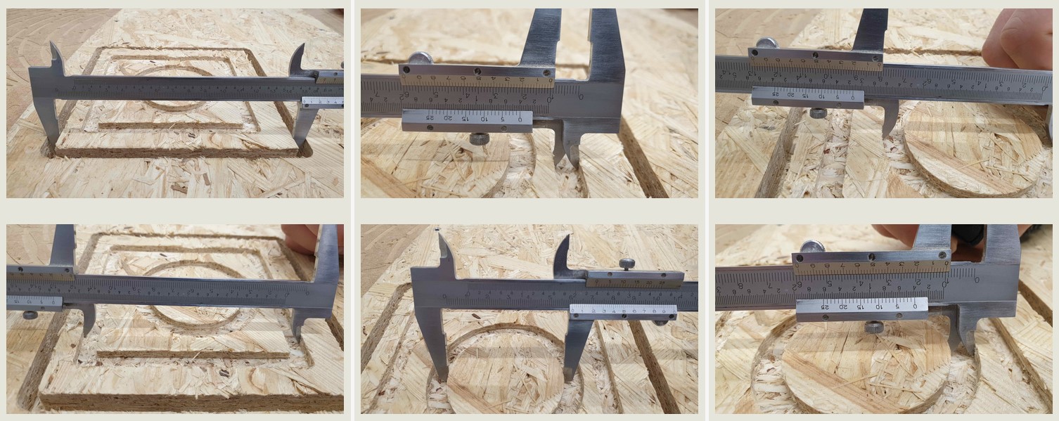
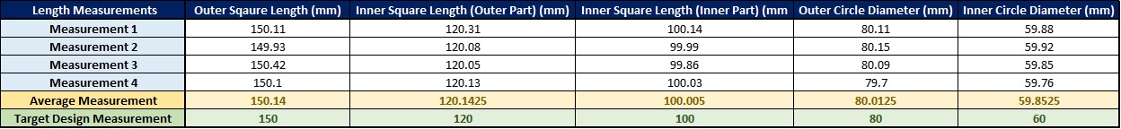
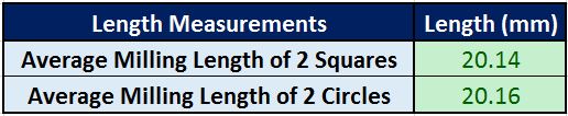
As seen in the detailed measurements table after the milling. The measurements were being performed of the outer square length, Inner square length, Outer circle diameter and the Inner circle diameter. The measured values were verified from the 3D design values and it was amazing to see the NC routing cut and engrave these parts at such precision. The Target 3D design values for the outer square was 150, inner square was 120 and 100 and outer circle was 80 and 60. All the values measured are close to the target values as seen in the table below and error is minimal in comparison with the 3D design file. We measured the average milling length for two squares and circle i.e. 20.14 mm (average) for square and 20.16 mm (average) for circle.
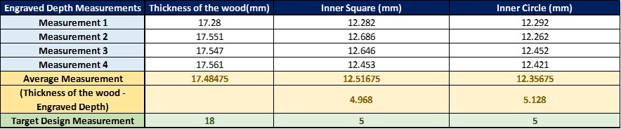
Apart from length measurements, the engraved area measurements were being performed for the square and the circle using the digital screw gauge. The results can be seen in the table below and the difference is observed to be minimal. The target design values in the 3D Design file was 5mm and the measured values after the milling were i.e. 4.968 (average) for square and 5.129 (average) for circle which seem to be quite precise.
Individual Task
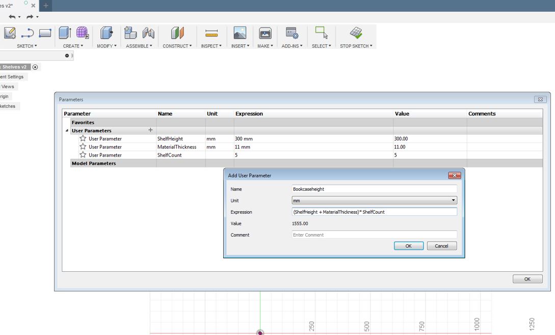
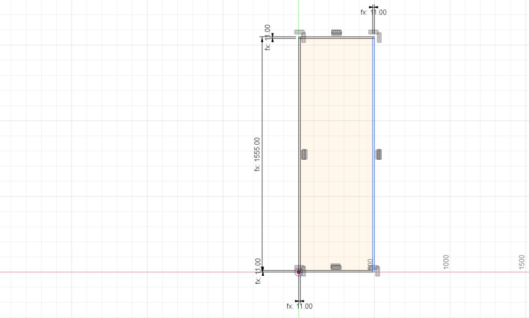
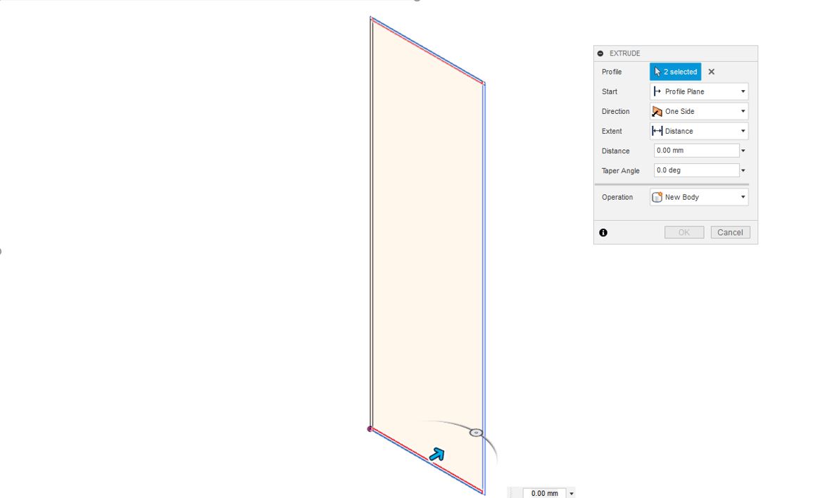
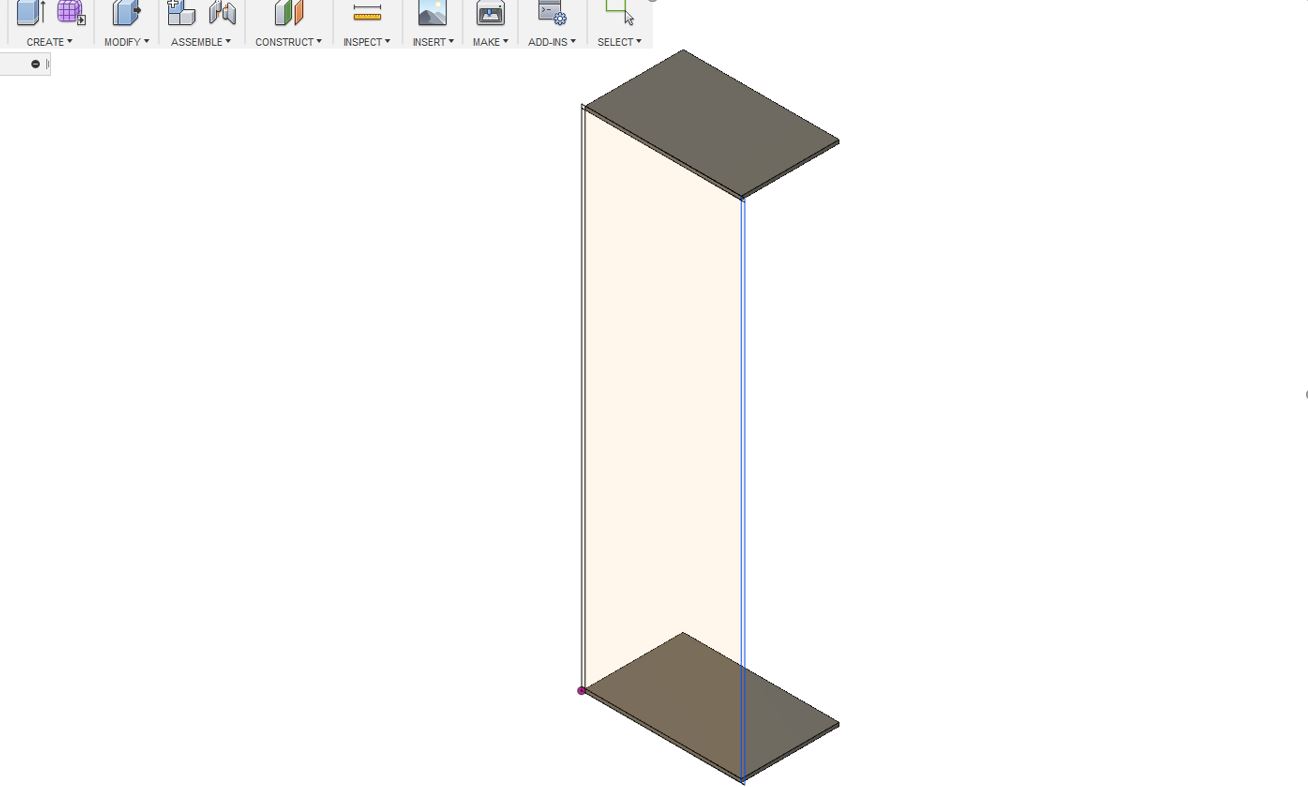
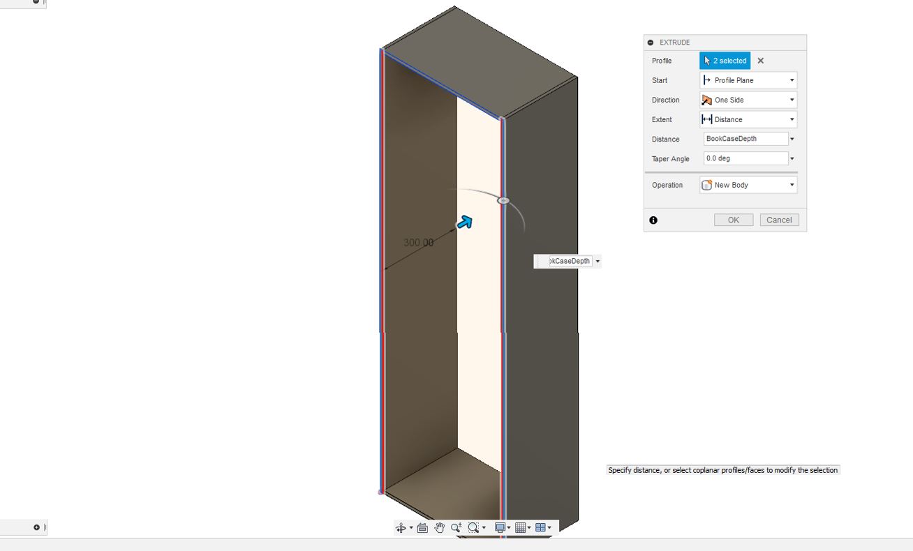
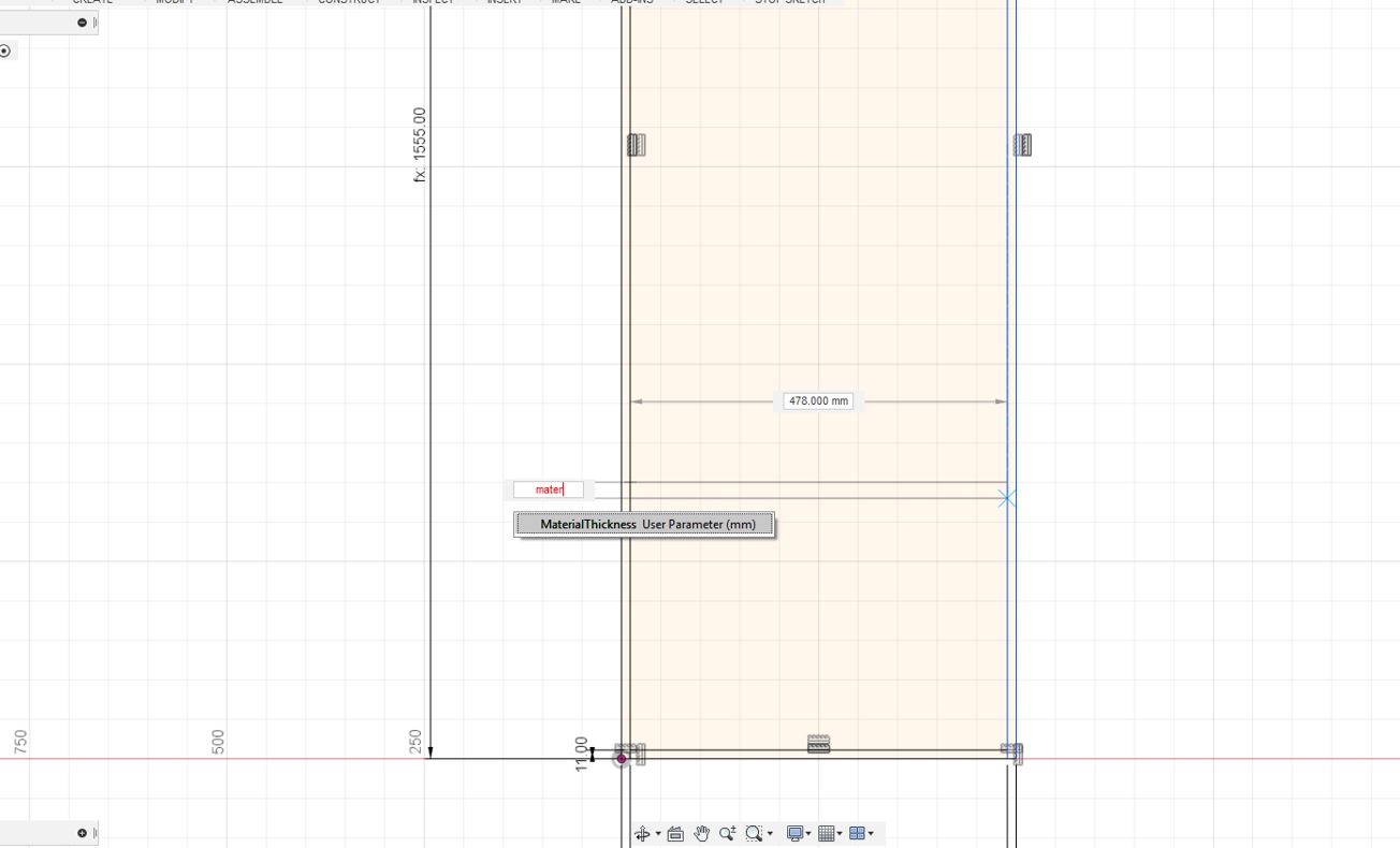
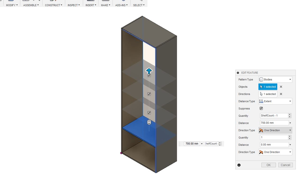
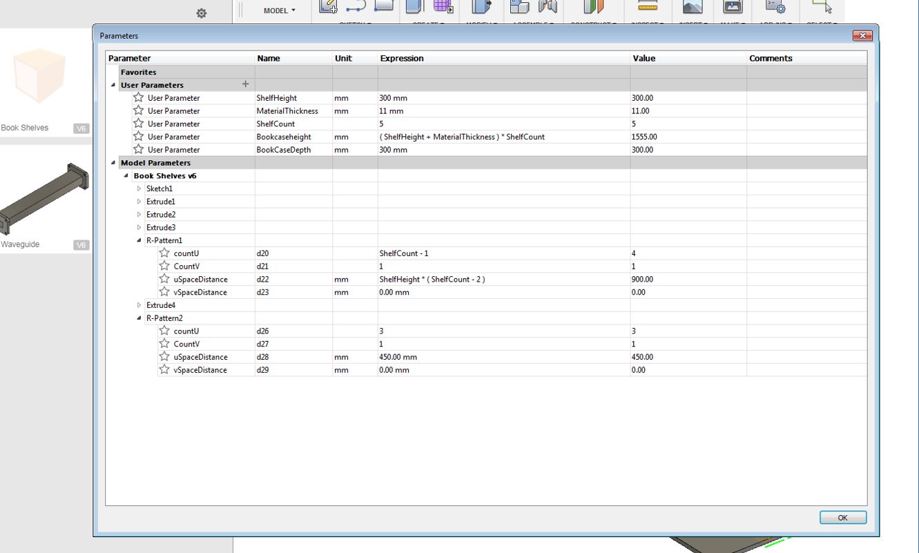
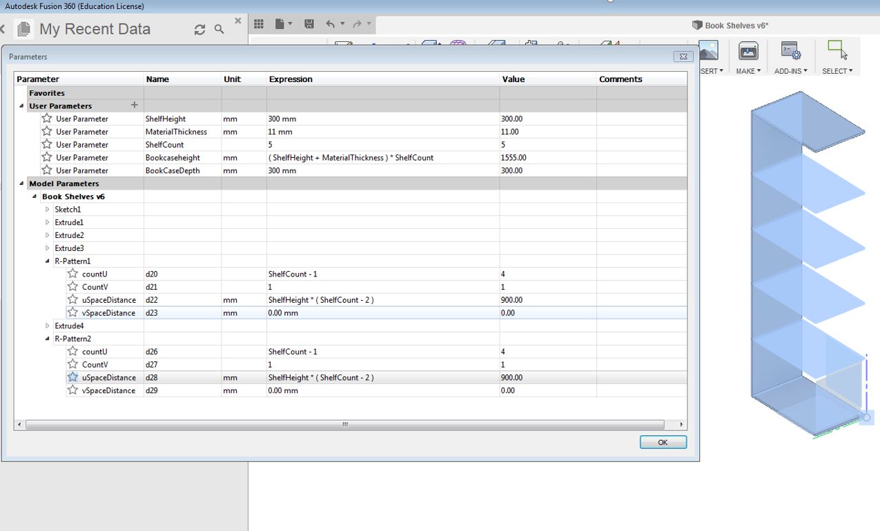
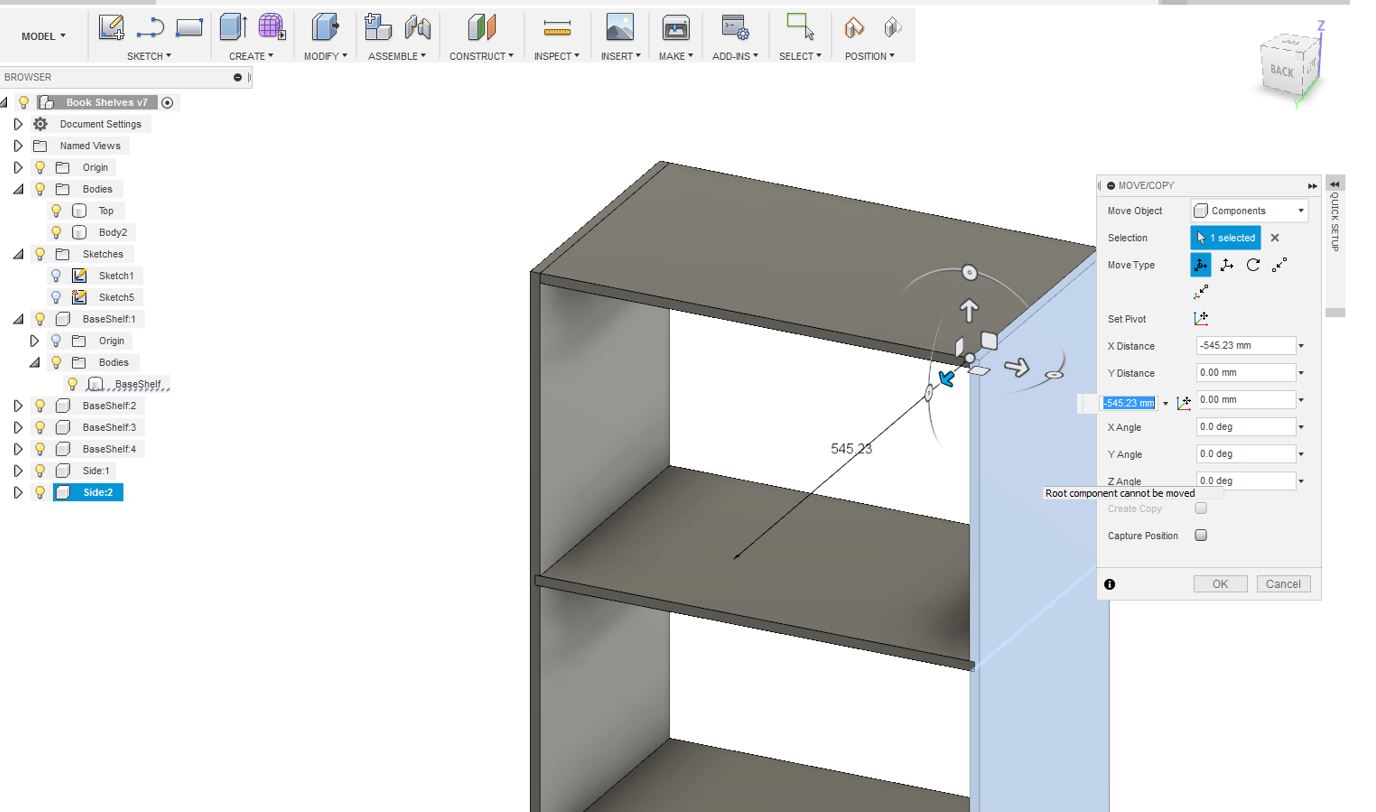
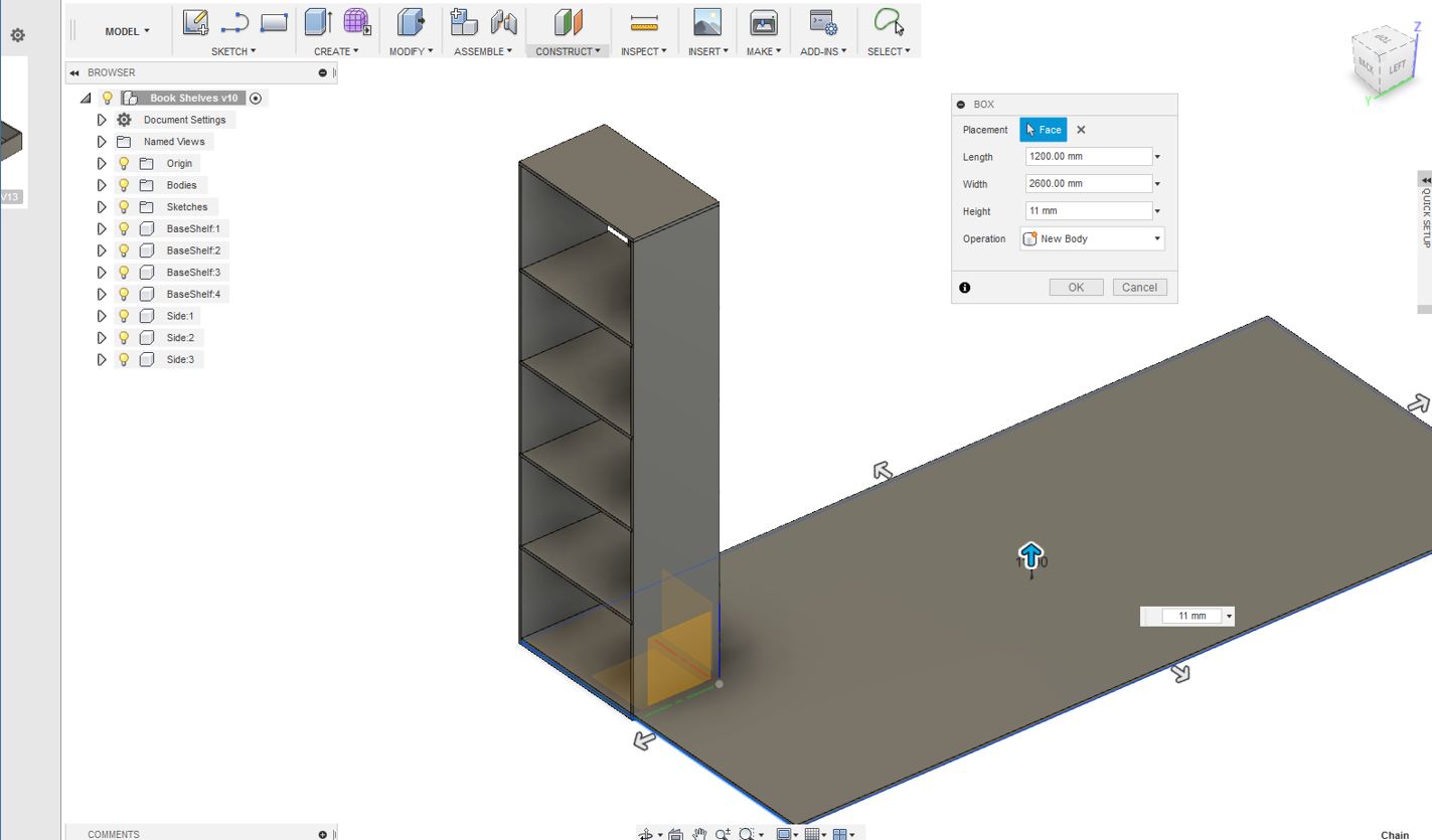
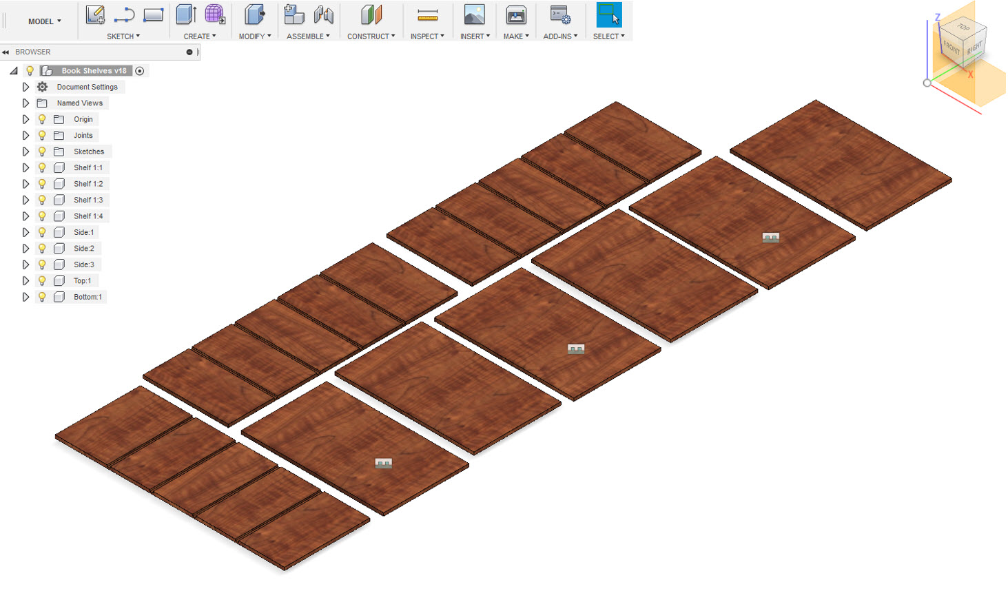
I really wanted to learn how to make furniture using fusion 360, especially how to create joints and inturn make something big. I planned to design a shelf for multipurpose. I kept the thickness of the material in mind before starting my design. I wanted my design to be parametric thereby at the beginning and every stage of my design the parameters were being defined for the design. I started my design by sketching a simple box shape. To understand and learn more about 3D designing in fusion360, my week 6 on 3D printing and scanning demonstrates a nice example for using fusion 360. Then creating a 3D model representation of that. I added the shelves necessary for my design. I defined te shelves as well to be paramter and at any time, I can increase or decrease the number of shelves.
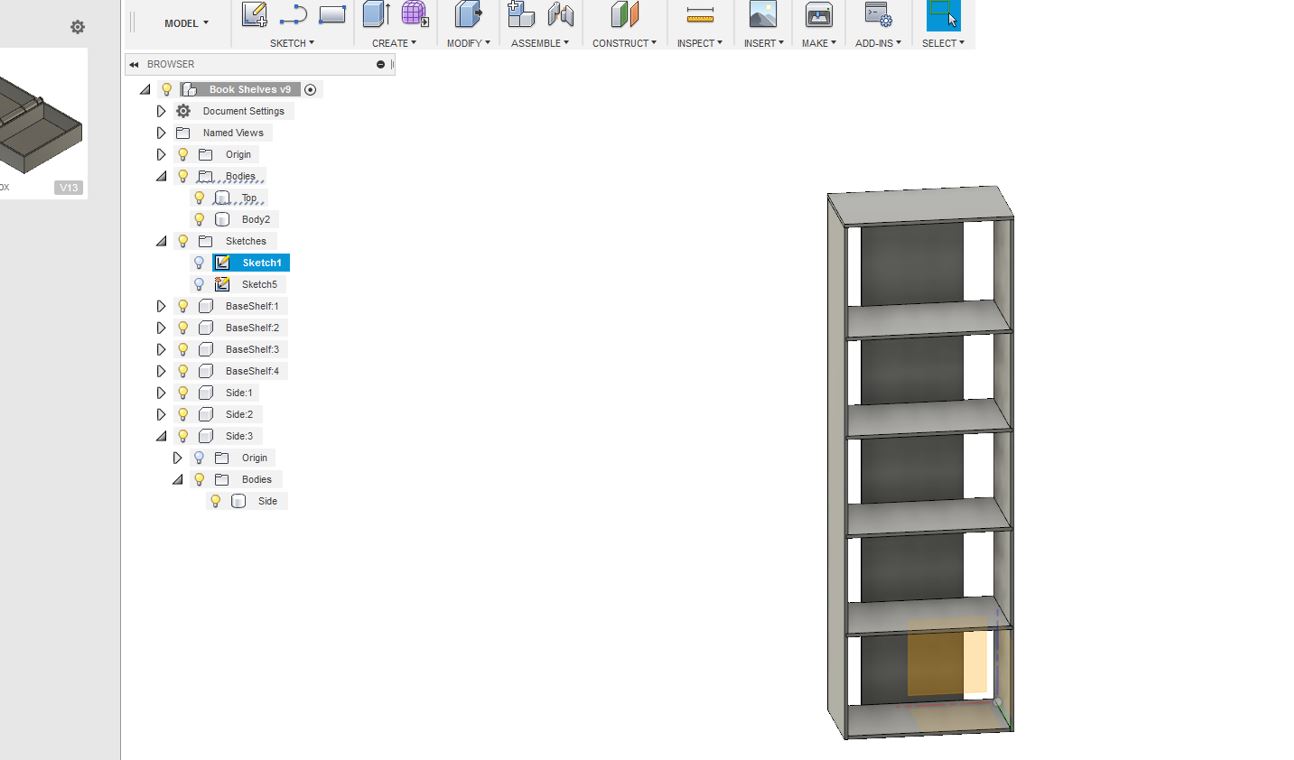
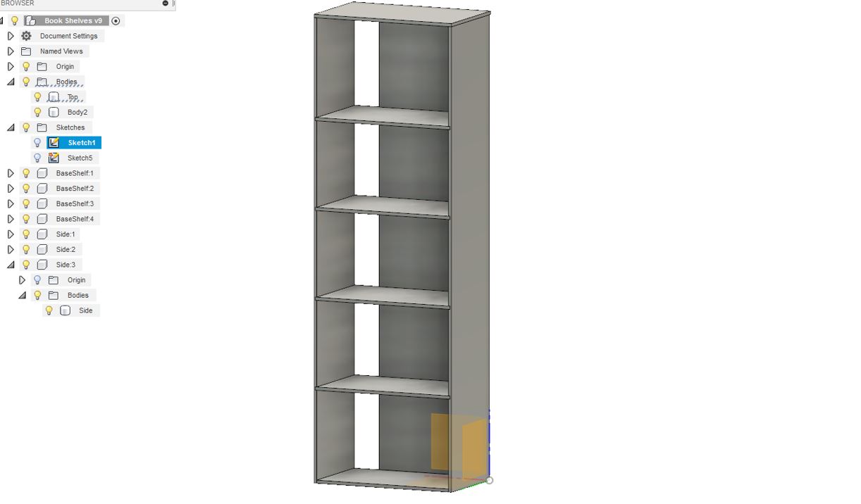
As seen in the pictures above, the shelf is almost ready and the Next step was to create a box feature to place the components in the plane since we are going to mill it and we shall know the size on the OSB Board. The OSB board used to make the design here is 11mm thick, it is 1200mm wide, and it is 2600mm tall therefore I made the box according to that. Since the design was paramteric and at any time I can shrink the size of my design. I noticed that my shelf design was large and it will not fit the OSB Board plane that I created thereby I adjusted the size of my design so that it can fit easily.
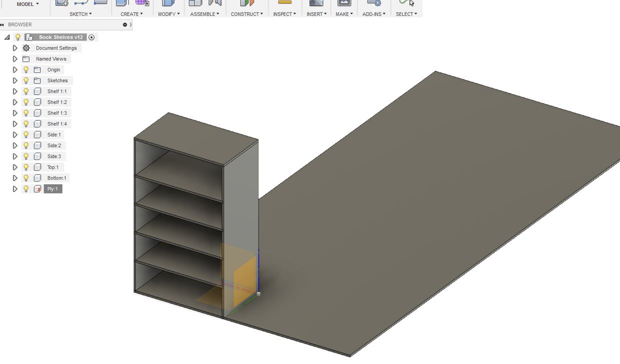
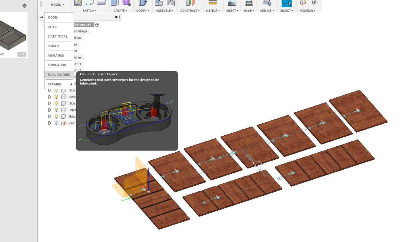
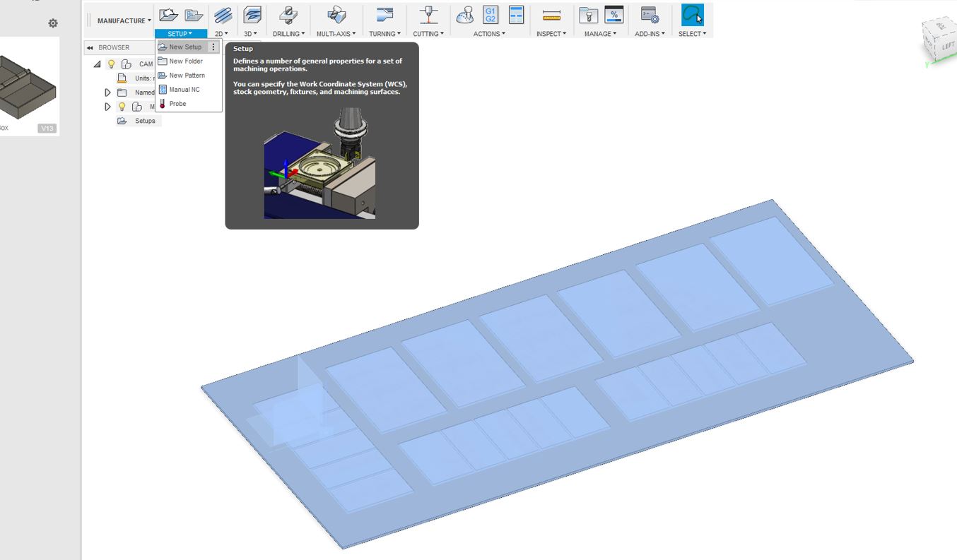
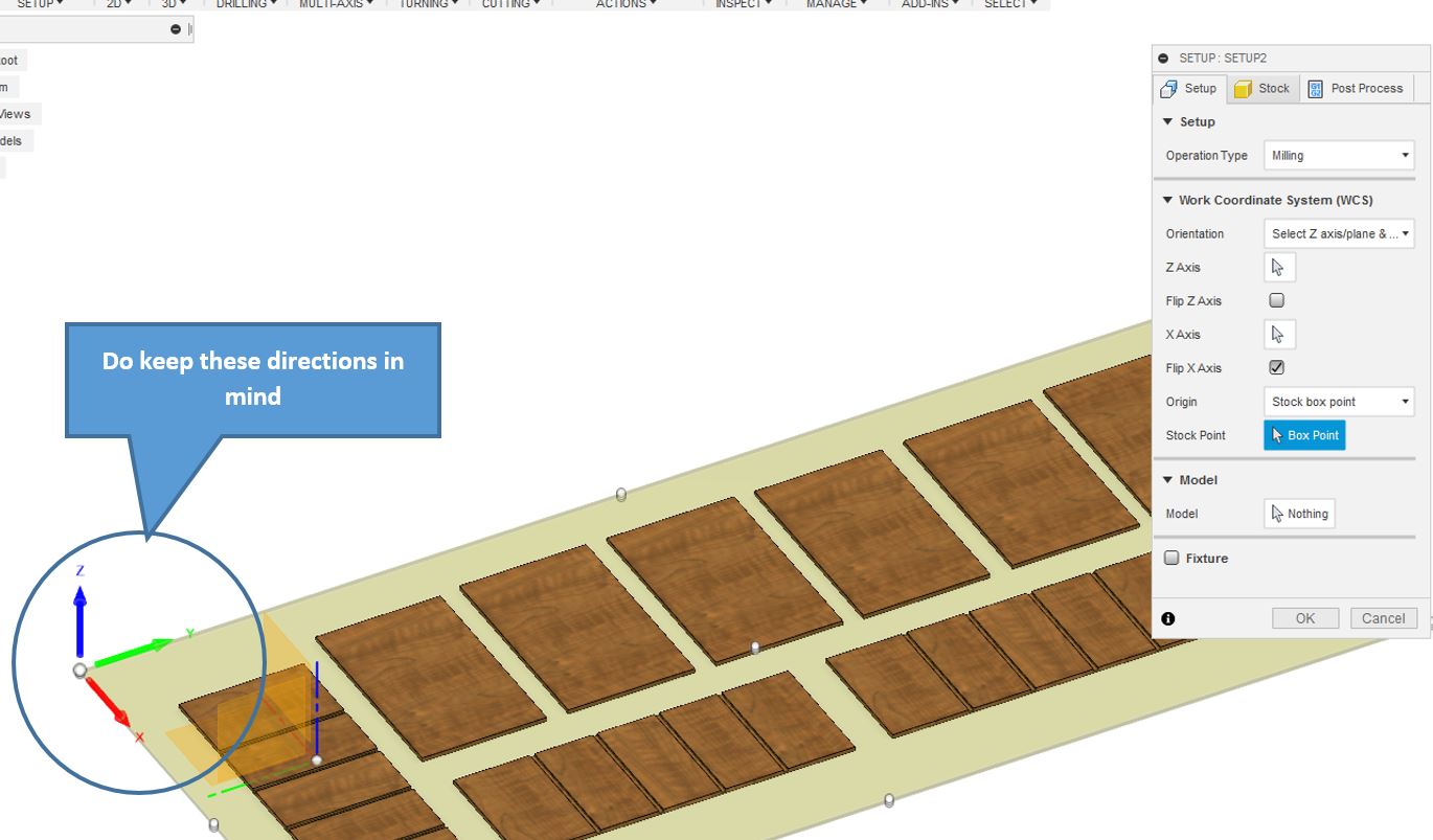
As seen my design has now been completely fitted onto OSB Board. The next step is to manaufacture it with the the New setup creation, setup settings and origin settings (For the Origin settings keep the and stock settings. which are mentioned below in the pictures
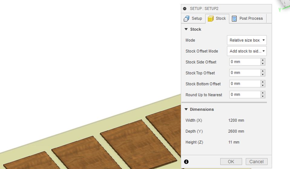
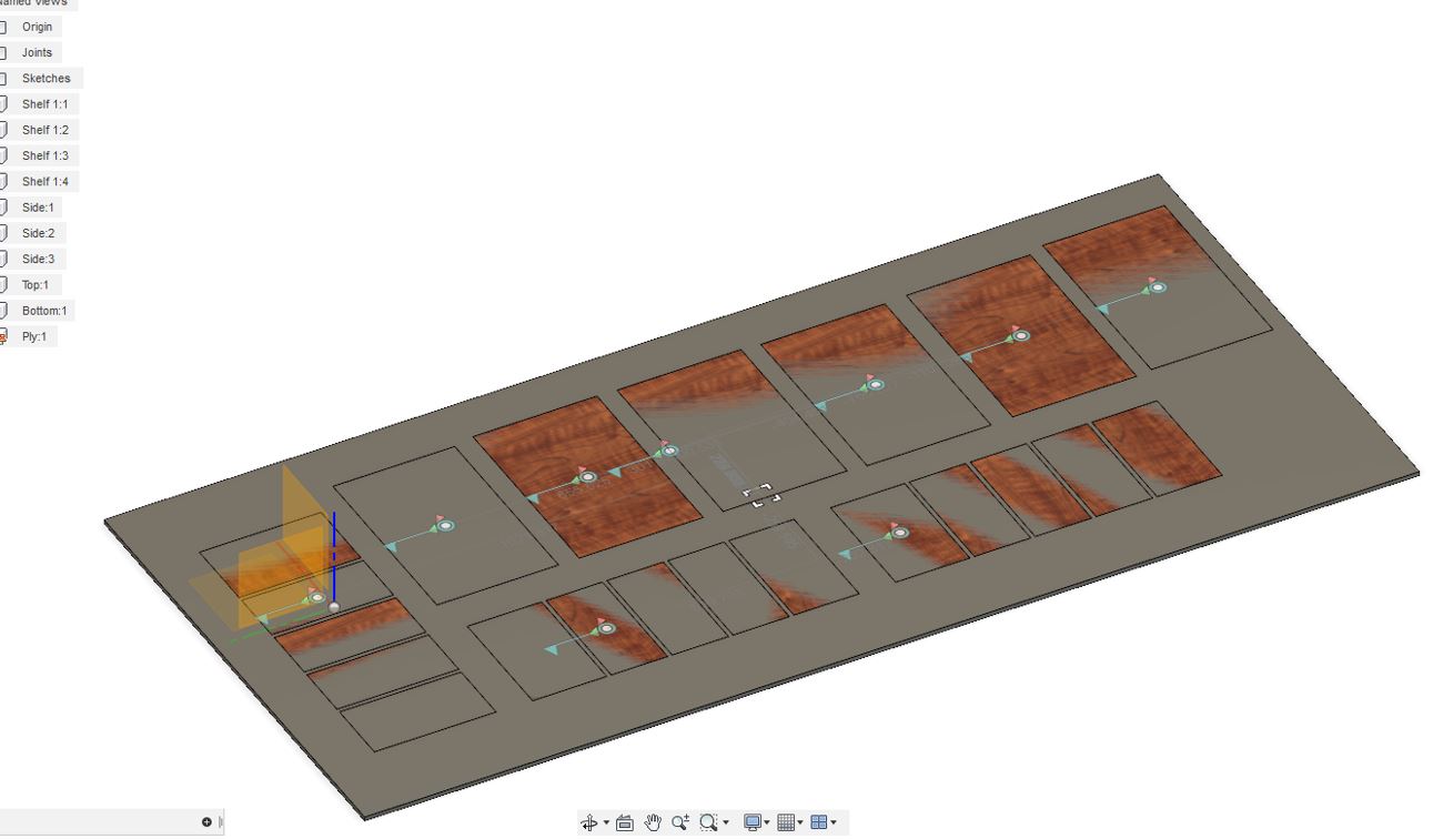
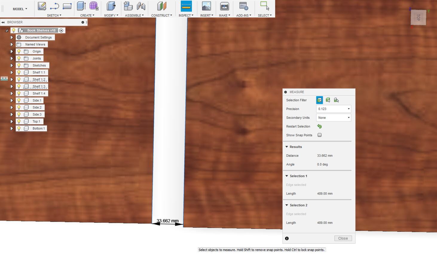
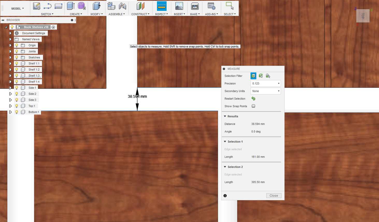
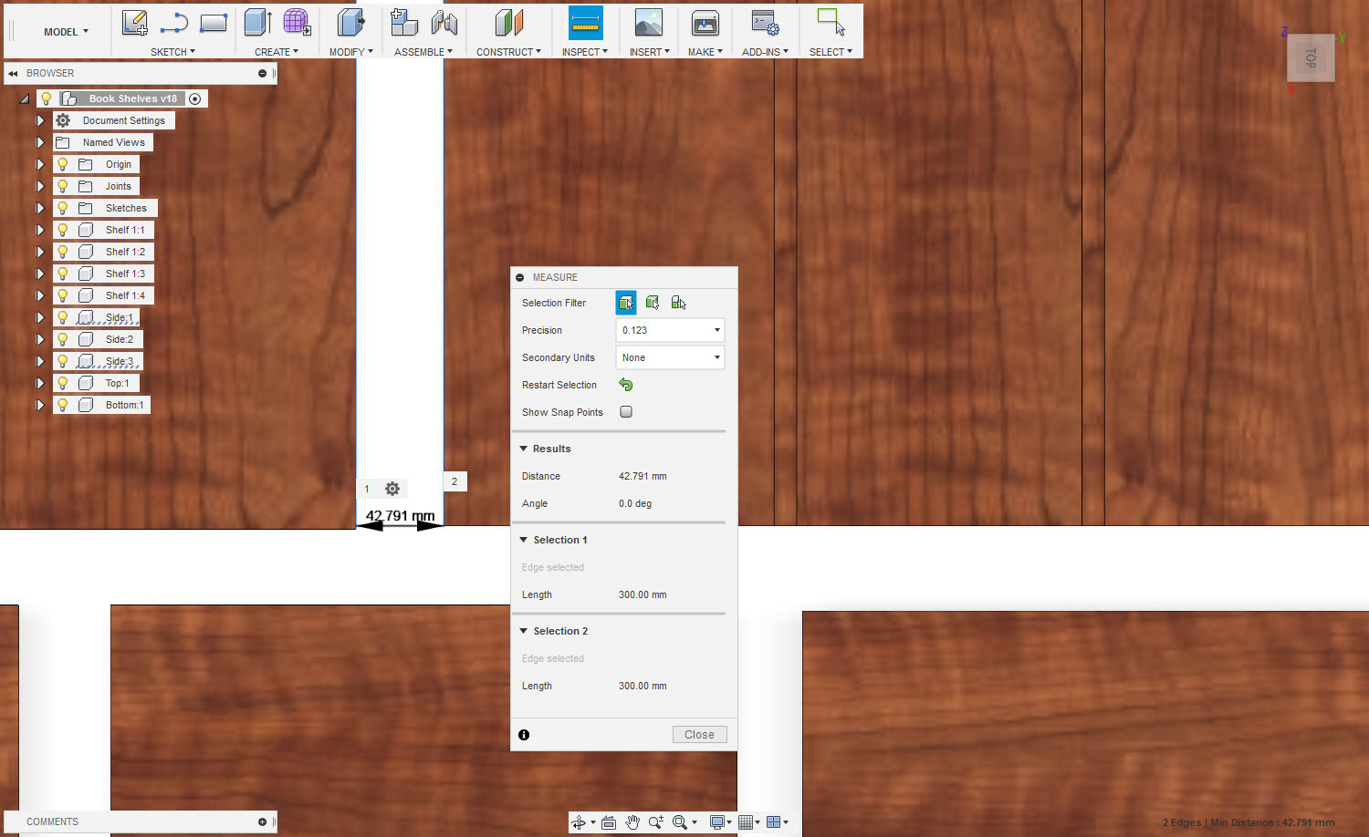
The OSB board used to make the design here is 11mm thick, it is 1200mm wide, and it is 2600mm tall. Nesting is very important inorder to use the OSB Board in an economical way and to avoid any wastage of the Material. I tried my level best to tightly pack the OSB Parts, Since it was my first experience of milling thereby I tried to leave a margin of 3 to 5 cm and I didn't wanted the parts to be overlapped, keep in mind that I don't waste any material.
For more better nesting VCarve Pro, is a nice software that fits the parts on the board in a economical way. The following Link describes more details about nesting with VCarve Pro.
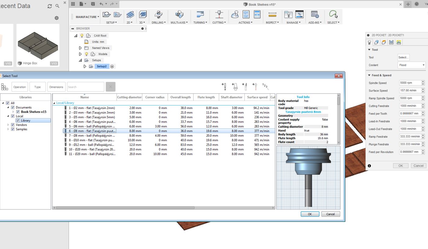
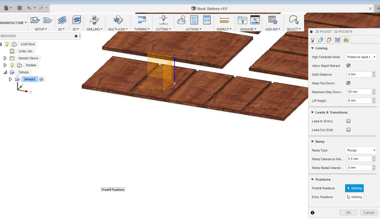
Below 2D Pocket Settings were done:After going throught the origin settings, the next setup is select the tool, we are going to use for our design. The tool we are using for our NC routing is 8mm in diameter with an overall length of 19.6mm. We were advised by out local instructor Eino that before doing anything we need to download two files from FabLab Oulu Wiki page to prepare for the milling:
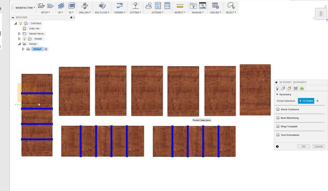
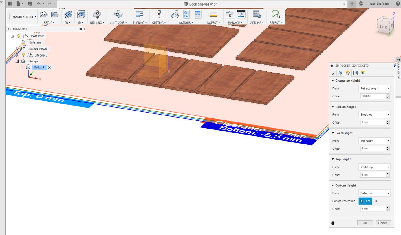
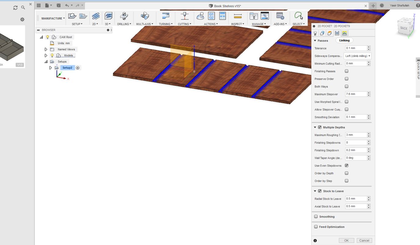
Also my design had some engraving thereby referred to as pockets. The Pocket Settings require selection of all the pockets and apply the Geometry, Height Clearance, Passes and Linking Settings which are seen below in the pictures.
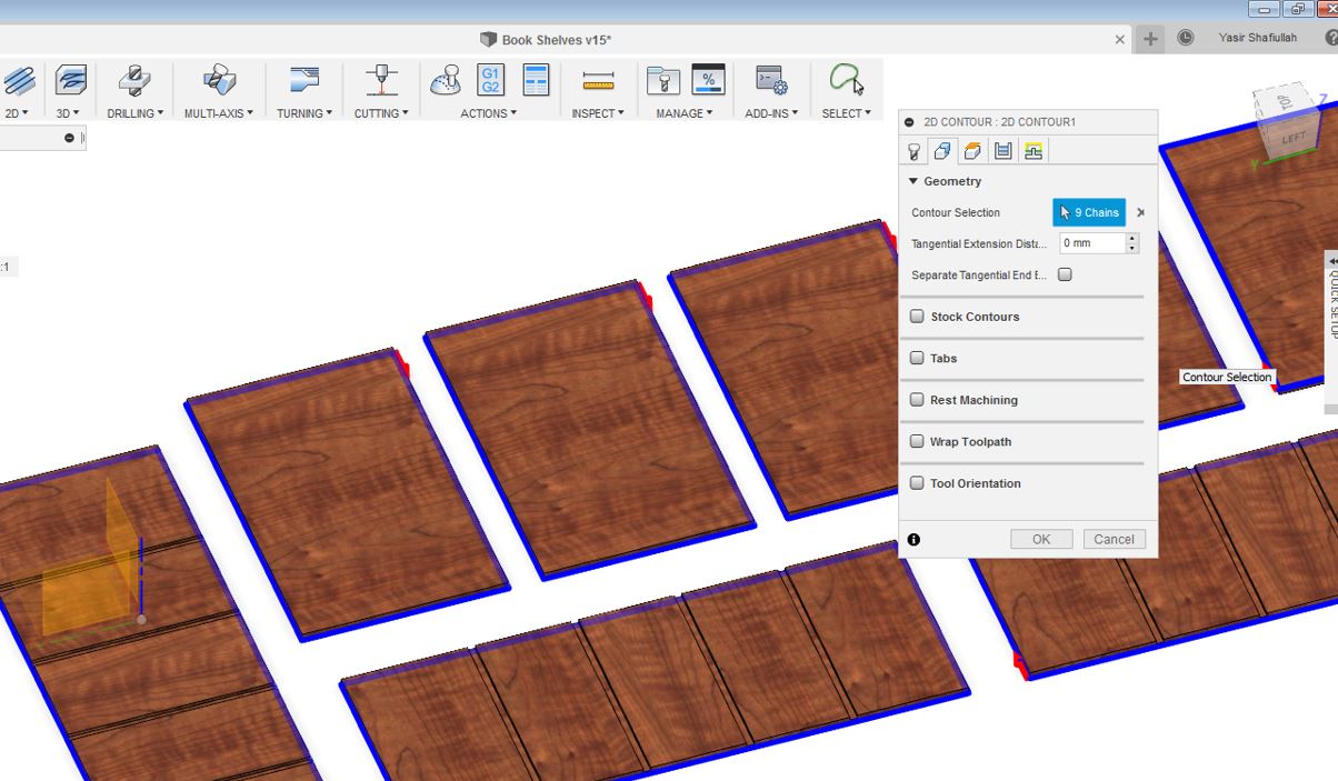
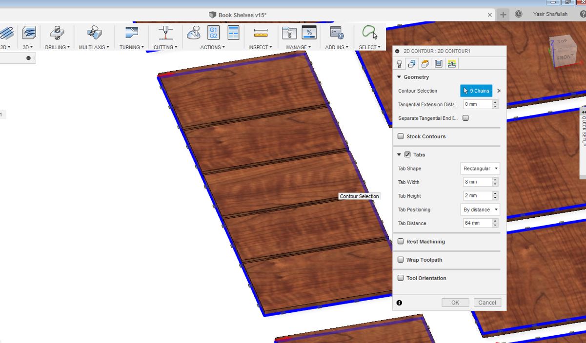
Below 2D Contour Settings were done:
To make the contour i.e selection of areas I required to cut, the geometry settings were necessary for that, thereby as seen below the necessary geometry settings are also necessary.
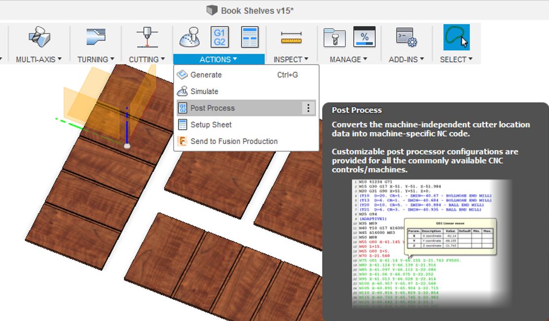
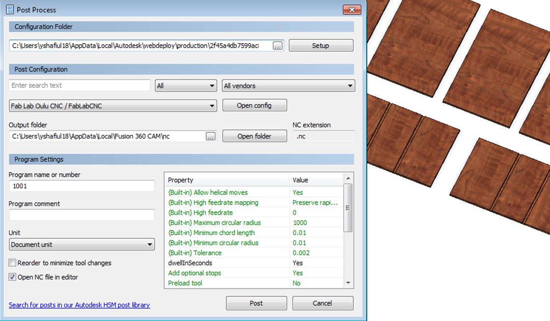
Post Processing Steps are as follows :
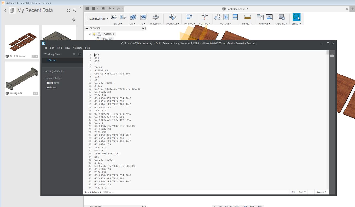
After the pocket and the coutour settings, the next step is the post processing. The below setups are mentioned to generate the .nc file format which will be used by NC Router for Printing.
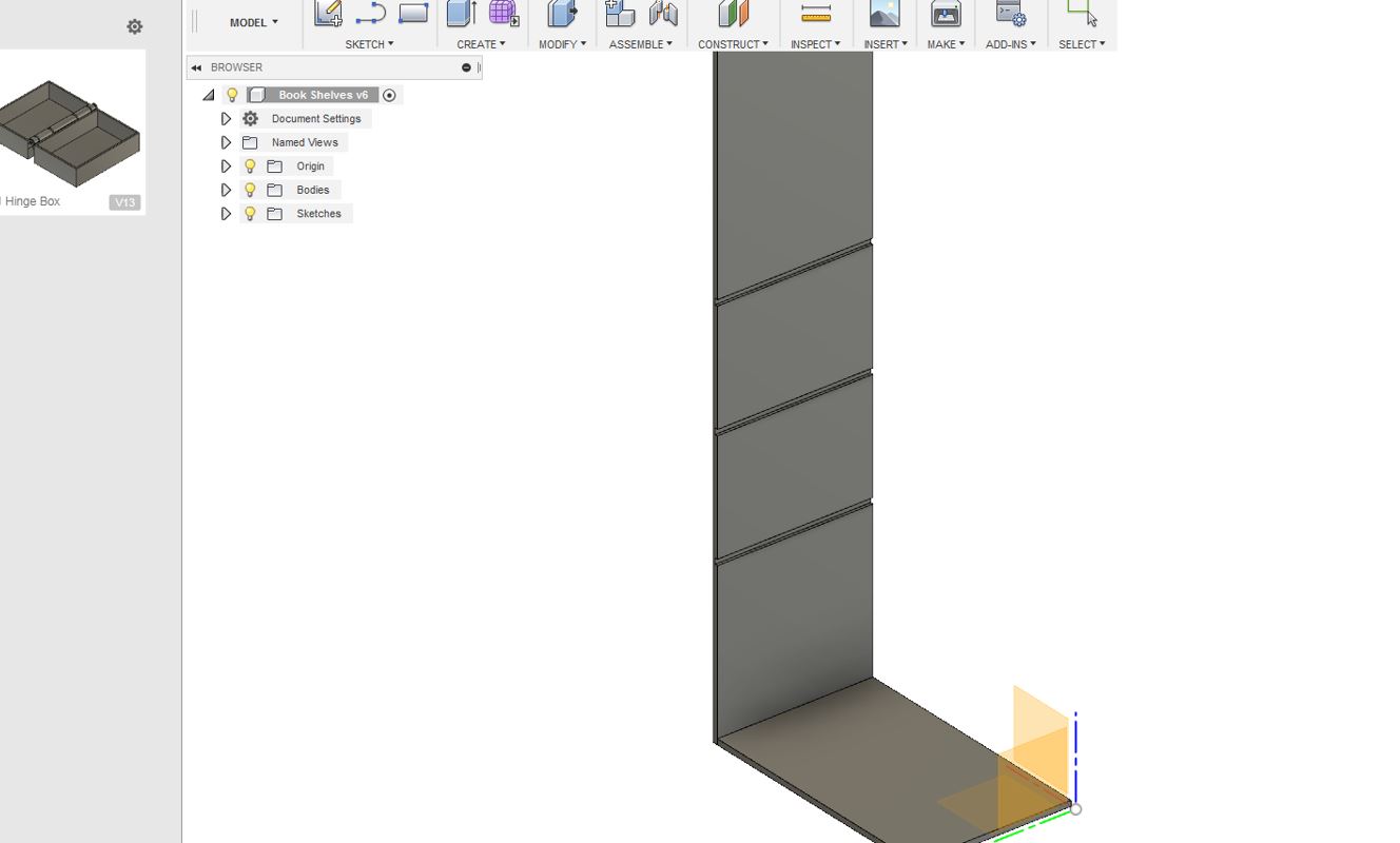
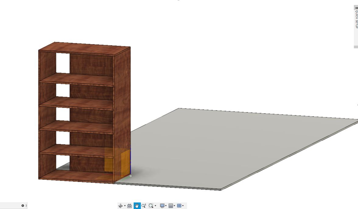
Below is the Book shelves design being done on Fusion 360:
Milling Process & Assembling
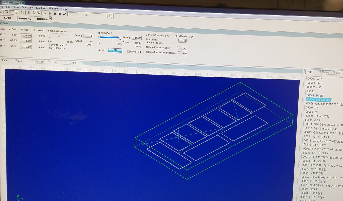
I did the milling for the design. For origin settings, I used automatic z-axis setting tool just as explained earlier in the group assignment, the steps will remain the same. The milling with the NC Routing Machine took 1 hour.
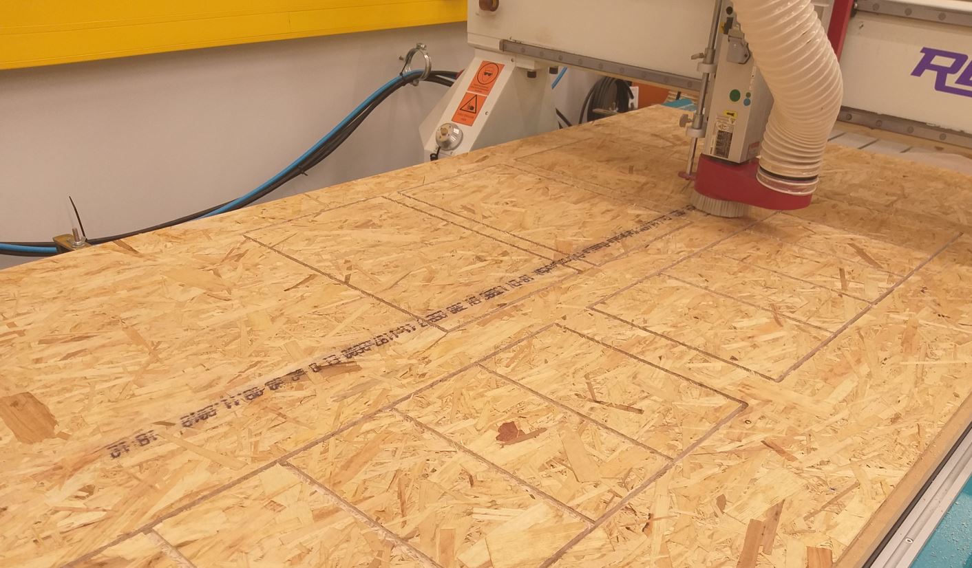
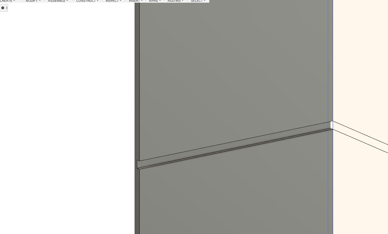
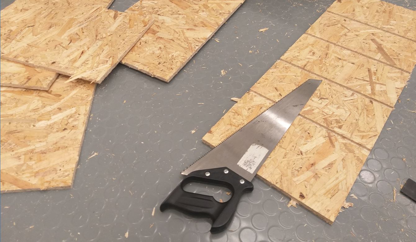
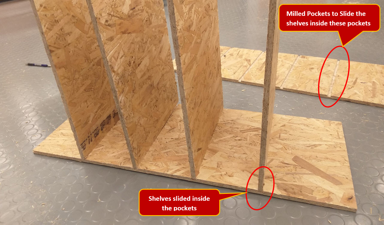
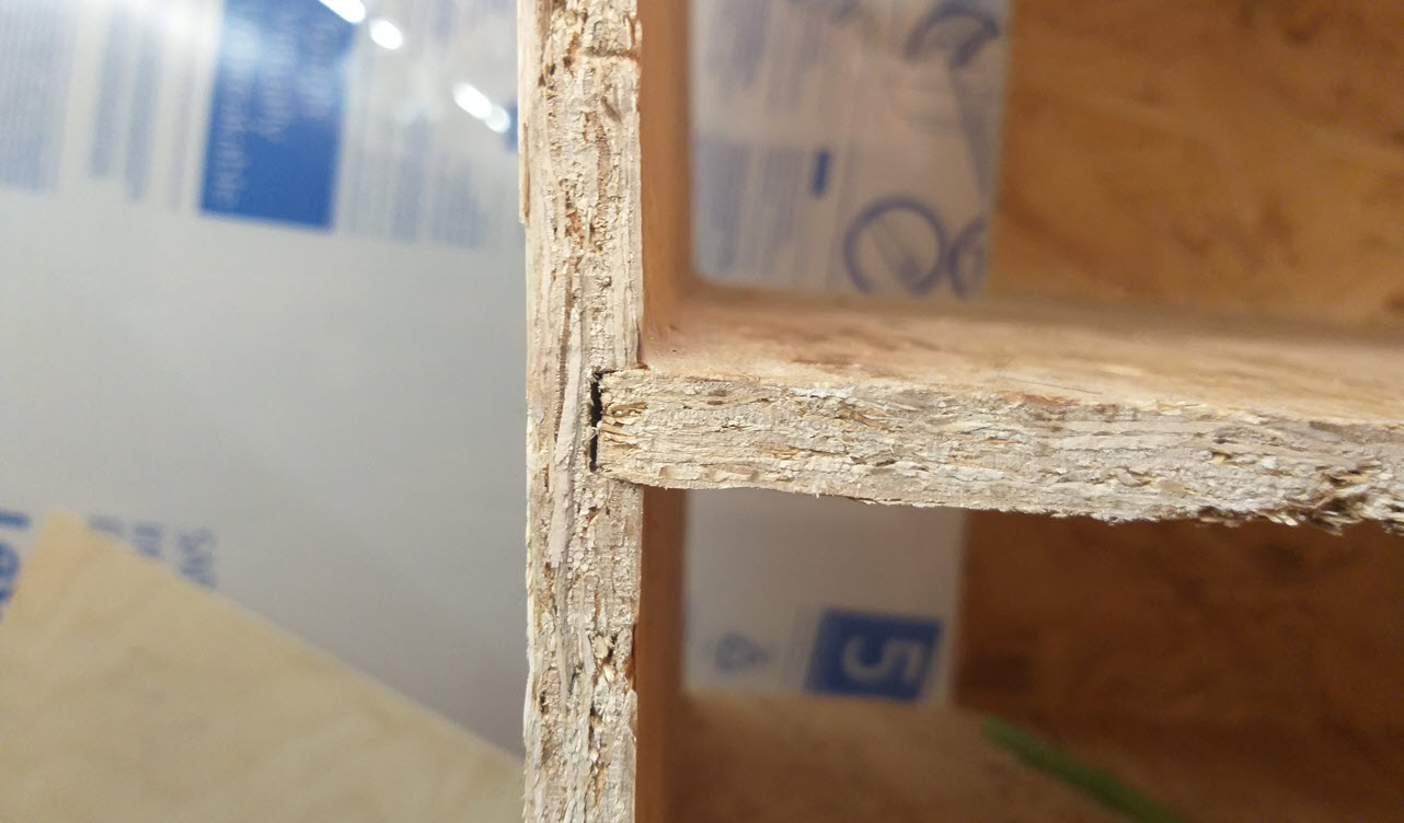
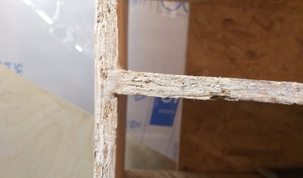
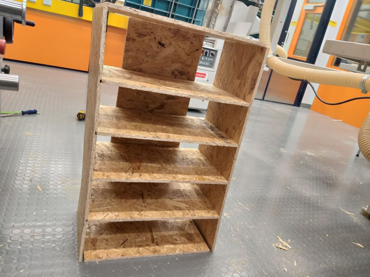
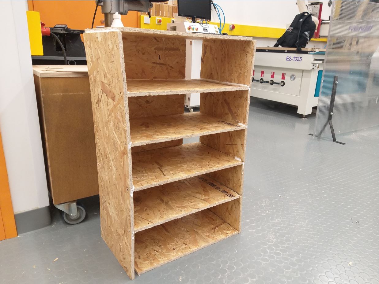
After milling, I removed all the wood parts and finish the edges by carpet knife. The shelves were then inserted into the pockets that I made specifically, it was a nice fit inside. The OSB was flexible enough and that with a little bit of hammering the pieces would fit together. Also I inserted all the shelves in all the pockets and then finally combined all the parts with wood glue and set it for 4 hrs. The project took the advantage of computer-controlled machining since the pockets cannot be made with the saw disk. Below are some pictures of assembling the Final Design of the Book Shelf.
Resources Utilized
- I utilized these resources for this task:
- Autodesk Fusion 360, for 3D Modelling
- CNC Studio software